Tuesday 4 September 2018

Radiator and Cooling - Pt 1

I've now started to fit the radiator and fan. Both of these have come from AK. I read on one of the posts recently that you can get rubber grommets from Rimmer Brothers (Part Number 500447) to sit the radiator on and can now confirm that these are really great and fit perfectly.

Shiny new rad and brackets
After minor adjustment brackets all fitted
Rubber grommets
Radiator and brackets installed
Done
Now onto the fan. The fan comes with a number of different options for fitting by either clipping to the radiator or by bolting top the chassis. I've opted to bolt to the chassis as this means that I don't  to risk damaging the core over time and also I can remove either the fan or the radiator independently should the need arise (hopefully not for quite some time).

First I positioned the fan where I wanted it to go although it's very close to the anti-roll bar and marked very carefully the 4 holes that will fasten it to the radiator support frames. These were then drilled and tapped and the fan offered up and bolted in position.

Fan bolted in place
However, two immediate problems. The first one is that the plastic grill of the fan is broken. Looks to have been done in transit at some point and that was very quickly sorted by AK who are putting a replacement in the post immediately. As normal fantastic help and service, nothing ever too much. The nest problem meant that I have to cut a scallop from the lower support frame as the rotation fan could touch which I really don't want to happen as this will cause problems. So. Off with the fan after marking what needs to be remove ant out with the die grinder to remove the metal.

Scallop cut out and smoothed
All painted
I'll have to wait now for the replacement fan before I finally fit the fan.

Next job is fitting the lovely stainless header tank. This is really well made and will look good in the engine bay.

Shiny new stainless header tank

Chassis rail drilled and tapped
Fitted

Just thought i'd add a picture of where the rolling chassis as of now.

Propshaft - Pt 2

Well, now had the opportunity to complete fitting the propshaft. This was one of the easier tasks and went without a hitch, the only fiddly thing was getting the bolts in place as it is very snug around the diff flange. I had to cut down the length of the bolts as the only ones I could get were a little too long and the ends were getting too close to the diff seal.


Just need to check if I need to add some lithium based grease to the uj's.

Tuesday 28 August 2018

Propshaft - Pt 1

Now that the engine and gearbox are in I have been able to measure for the prop-shaft. I, like many before me have opted to go to Bailey Morris for mine. I took a number of photos, created a couple of slides and filled in as much as possible on their data sheet then phoned, had a great chat, sent the info and placed the order.


I have a Tremec TKO600 gearbox and the diff is a 3.54:1 PowerLoc XJ40. The gearbox spline has 31 teeth.

Space for propshaft

Gearbox nose
Diff end

After just 3 days I have a lovely parcel arrive.


All I have to do now is to remove the rubber bung in the end of the gearbox and assemble the propshaft.

Monday 27 August 2018

Power Steering Pump - Pt 2

After having a chat with Jon at AK the position for the Power Steering pump has been sorted. Just in front of the steering rack behind the rad and fan and supported by a bracket bolted to the nearside chassis rail.

First thing I had to do was decide how much of the old bracket I could use which turned out to be around 40%. So I set off cutting off all the areas that were not required. The original bracket now looks like this.

Before
After. Lots removed. Need to add a small tie to the two straps
Now I need to move onto the mounting bracket that the original part will be welded to. I spent quite a while sorting the position I wanted and then mocked up a bracket in cardboard.

Cardboard mockup
Then I went onto the trusty CAD and modelled exactly what I want with a few mods.

Modelled in CAD

Drawing ready for laser cutting and welding.
Got a quote from Profab in Coventry for £50+VAT which I am happy with so ordered one. Now just got to wait a week or two as its holiday time! When I get the new support I'll have the original bracket welded on top and then the whole assembly powder coated black.

Tuesday 21 August 2018

Heater Control Box - Pt 1

I have it on good authority that I must have air capable of being directed to the feet and screen (bosses requirement!). Also heated seats! Still, this is about the air box.

I could have gone down the normal route of using the fibre glass cover etc but wanted to do something a little different.

I spent some time working  out what size I wanted etc and then came up with the design (normal belt and braces stuff) that I was happy with.

As is normal for me I sat down behind my CAD screen and had a bit of a dabble.

Outside of new heater box
Inside of new heater box
Laser layout with all parts unfolded
Now for the next phase, manufacture. I have chosen to have all the parts laser cut in 1.5mm thick aluminium sheet by a local company in Coventry. They have done a great job and it only took a few days to complete.

The parts as they arived
Obviously I have to get a number of other parts but most of those are sourced from eBay. Now to the making of it.

I have a small sheet metal folder/shear which has proved invaluable so images below of progress.

First parts folded. Make sure you fold them the right way else the part will be reversed!

Riveted and sealed together

Bearing bosses added for the variable baffle plates

Hose nozzles (from Screwfix)

Nozzles bonded in

The start of the internal mechanism

Bit more progress. Shame its backwards! Did I mention that you have to bend it the right way round

Parts of the deflectors

Both finally complete
I'm happy with progress and it looks to work OK too. Still got a bit to do but I'll finish that a little later.

Gearbox Mounts - Pt 1

I have never been a fan of simply drilling and tapping into the chassis rails with larger screws so decided to do it a little differently. I have had a couple of bosses made that will fit in through the top wall of the chassis rail and sit on the inside of the bottom wall of the chassis rail and then be fully welded on the top surface. These pillars are 25mm diameter and have an M12 tapped hole in the bottom.

Pillars and bolts. I'll use spring washers and loctite

25mm hole in the top and 12.5 in the bottom and through the gearbox mount plate.
First one in ready for welding


Bolted up with temporary braces removed. Just needs welding.
I'll get the welding done a little later as I want to get all necessary welding done at the same time. I will have a small boss for the handbrake cable mods, the side-pipe mount brackets and the gearbox mounts that need welding.

Engine - Pt 12

Quite a nice long update today after a bit of a lull.

Well the engine has now been run and in and setup on the dynamometer. The firing order had to be changed to 351 spec rather than 302 as I had it. The timing was set and a few setup changes on that too but the carburettor was pretty much spot on.

Peter and Knight Racing did the testing and seems happy with what I have built which is very satisfying. The results are as below.


I must say that I am really pleased with the result. More or less 450 bhp and 426 ft/lb should be adequate....

Now it needs attaching to the gearbox etc and finally fitting into the chassis.

So, onto the next task.

First thing I did was to attach the flywheel. At this point I can dial in the bell-housing to make sure the input shaft of the gearbox is less than 0.005" runout. Initially when I set it up to measure the runout it was about 0.018" out in the worse case. Now, after selection and fitting a set of offset dowels it is very much closer and fully within tolerance.

All dialled in.
0.007" offset dowels from Stateside Autos of Nuneaton.

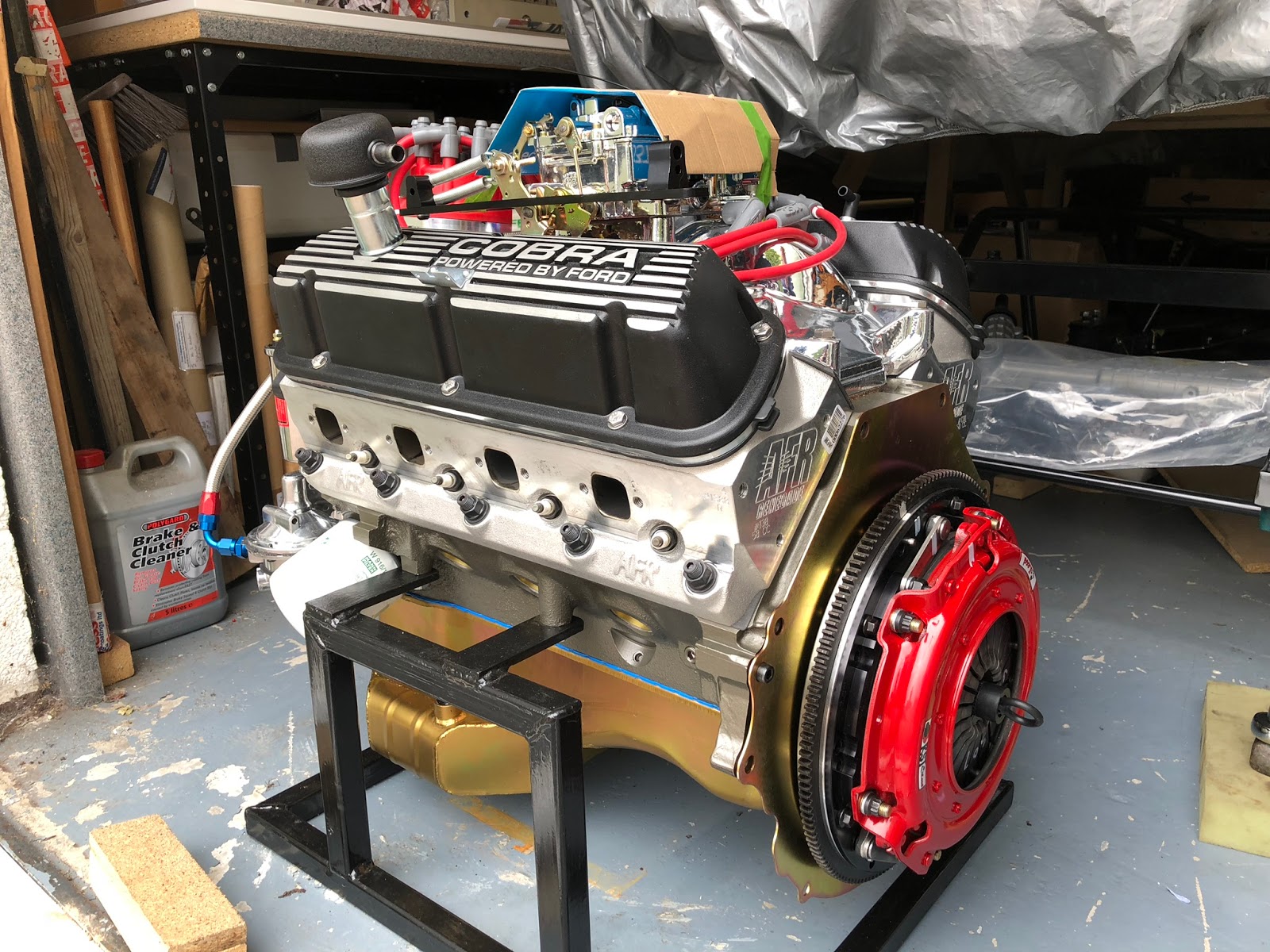
So now I can go ahead and fit the clutch assembly not forgetting to very closely follow all assembly instructions and final torque settings. I have chosen to fit a McCloud twin plate clutch with hydraulically actuated lever arm.

Back-plate, flywheel and first part of clutch
Fully fitted clutch

Pivot installed
Bell housing fitted although I have forgotten to add the actuator bracket!
Clutch release lever and bearing fitted
At this point my patience was somewhat tried. Could I get the gearbox to engage through both plates! Oh no. No chance. I had spent a lot of time making sure that all was very carefully centred and that I didn't push on the pressure plate springs when trying to fit the gearbox (which I must have done as the back plate moved.... again). In the end I gave up for the night, had a cup of coffee and relaxed only to begin battle tomorrow.

Just about to lift the and align the gearbox
Finally fitted after much effort and frustration
I ended up making some dowels out of long bolts so that I could slide the gearbox along these keeping it level and central. There were two of us doing this in the end and with Pete's help and the thought "why not depress the clutch lever, I have nothing to loose!!" it slide on so smoothly and we were able to bolt it up permanently. Boy, that was a relief to get that done. I was all ready to call it a day but Pete had come over specifically to help me get the engine/gearbox assembly into the chassis so we persevered.

In the air and removing the engine frame
Nearly in. Lots of gently manoeuvring back and forward and up and down

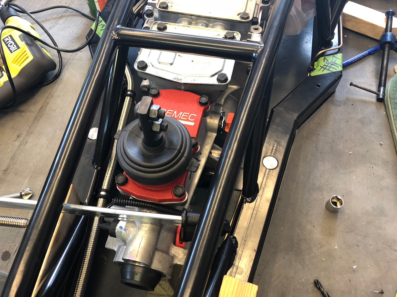
Nearly there although there is a clash with the fuel pump and I squashed the brake pipe. Oh well can't be helped.
Fuel pump and brake pipe issue. Needs to be sorted.

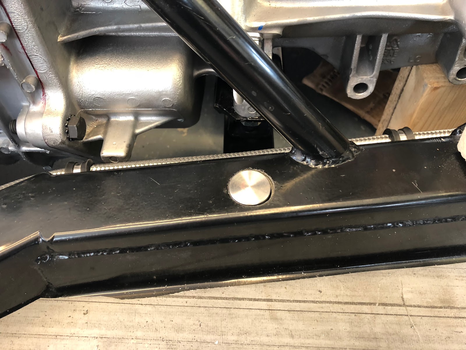
And there it is in its final position along with make shift gearbox mounts.
Finally in and fitted. Thanks Pete, couldn't have done it without you.