Friday 25 November 2016

Engine - Pt 7

Just a quick update today. Well I have finally had the opportunity to remove the sump and install the oil pump drive. Didn't take long just shouldn't have been necessary. Still the sump is now finally buttoned up and re-torqued to the correct settings.

After I spun the engine back over I thought I would just drop on the inlet manifold to see how it looks. I must say that I am really pleased with the overall effect. I know for the purests the block should be Ford blue but I am happy with my choice.


Earlier this month I was able to pick up the pulley set, alternator and a few other smaller items.

When I get a spare minute or so I will add a few more photos.

At least it feels like I am making progress finally.

Thursday 3 November 2016

Engine - Pt 6

One little thing you mustn't forget is the oil pump drive shaft. Really important to have the small pressed on collar to stop it being lifted out and dropped into the sump when the distributor is removed but more important is to fit it in the first place!!!

So.... off with the sump and the oil pump and in with the drive shaft!

This is the offending part. Such a small part but such an important job!


I've had a little more time than expected recently so I've been able to press on with my engine build. It's now time to fit the heads, roller lifters along with the ARP head stud kit and Felpro head gaskets.

AFR Cylinder Heads
Lunati lifters
Everything was very thoroughly cleaned in preparation for inserting the head studs. The threads were cleaned out and studs test fitted in each to make sure they all fitted correctly before final installation. I've opted to go for the ARP 12 point studs for the cylinder heads. As directed I applied ARP thread sealer to the studs that break through into the water jacket and then screwd them in to hand tight. The outer studs had a little ARP thread lube to aid screwing them in as well, again hand tight. Then I dropped on the head gasket carefully.
Studs all in and hand tightened
Head gasket in position ready for lifters and head


Next the first four lifters are assembled. These have graphogen on the roller and diameter of the body. Also liberally coated with oil too.

Then the head was carefully lowered onto the studs and two head dowels and the washer caps were assembled into their counterbores. Several of these were a little tight so a bit of very careful manipulation of stud and head was needed to make them slide home properly.

First head on finger tight
Lifters assembled
Now it is a process of 'the same again' with the other cylinder head. All went pretty smoothly. When both heads were on it was a matter of torquing the heads up in the sequence specified but in 3 equal settings upto the 80ft/lbs recommended by ARP. This was then double checked later just to check that all is OK. I'm using the excellent book "How to Rebuild Small-Block Ford Engines" by Tom Monroe. This has a wealth of knowledge and has been really helpful.

Heads on, all torqued up and double checked
Water pump trial fitted


State of build so far shown in the left picture and in the right the water pump loosely fitted as I was checking the bolt lengths from the stainless bolt kit I bought for the engine. Sadly three of the bolts are too short so these have to be relpaced. Now waiting for them to arrive.

There was a bit of a story with the water pump. I bought this just over a year ago from Summit and very pleased with it I was! When I came to fit it last week I realised that the flange shape of the pump did not match up with the timing cover. After much irritation and mixing and matching of gaskets I came to the belief that the pump was the wrong one for my engine. So up it went for sale and I started looking for a new pump, this thie I started looking at electric ones.

I put this up for sale on the UK Cobra Forum and quite quickly got a reply which was actually a question. It said "do you have the metal back-plate?". At that point the penny dropped and I realised that what I had assumed was a 'delivery/protection cover' was actually the backplate. Now all fits great and although I felt pretty stupid the situation is resolved. My wife was particularly pleased as she didn't know I make mistakes!!!

So, all's good in the end.

Just got the new bolts so all I need now is time to fully fit the water pump.

Tuesday 18 October 2016

Engine - Pt 5

Been a bit of a wait for the next instalment! Work has been busy and what with holidays and the like not had a lot of time for the engine. Still finally got some time so have been making steady progress with the engine build. Had a few parts to order so these have also added to the delay but they have now arrived so I can progress.

One of the things I was waiting for was the sleeve below. This had proved invaluable and made assembling the piston assemblies a relatively simple process.


Piston No 1 in. The rest will follow in short order.


All in and correctly torqued to the ARP specifications using plenty of the assembly lube as directed.

All con-rods correctly torqued
Pistons all in and complete.

Next I added the cam retainer plate making sure it was the correct way round and with plenty of assembly lube on it as this will not be run for a while.

After this the next job was to assemble the timing chain assembly. This was quite a fiddly job as the centre distance is very tight ensuring no slack in the chain assembly once assembled. I carefully aligned the camshaft this the fuel pump eccentric dowel at 6 o'clock and the crankshaft with its woodruff key (which took quite a while to fit as this was very tight and needed a little adjustment to make it fit correctly) at 12 o'clock and also with piston no 1 at TDC. When all was double checked, I aligned the marks on both pulleys separating them as much as possible whilst sliding both pulleys onto their respective shafts at the same time. All went OK apart from one thing. The crankshaft was supplied with 2 different length dowels. Naturally I chose the slightly shorter one as I didn't want it protruding past the end of the pulley interfering with the washer and bolt. One thing I forgot was that this dowel also drives the fuel pump eccentric so off it had to come and in with the longer dowel. 2nd time went a little quicker.

Timing chain fitted
Make sure the dowel protrudes for the fuel pump eccentric

Fuel pump eccentric now on and torqued as specified.
It was at this stage that I intended to temporally fit the heads and measure for the pushrod length, but basically I forgot and got a little carried away by fitting the timing cover and then the mass damper.

I had waited 3 weeks for the crank nose adaptor to take the camshaft timing wheel so now won't be needing that (as I'm not pulling the damper off!) but will now need to make a new adaptor.

Oh well, more haste less speed!

The next pictures show the engine with the timing cover and mass damper (Fluidamper) fitted. Tightening the damper was pretty hard work as this needed to be tightened to 110 ft/lbs (as per ARP instructions) but at the same time having to stop the crankshaft rotating. Still, no issues. All fitted well first time.

Meant to say I coated the fuel pump eccentric with graphogen and liberally coated the timing chain with oil before fitting the timing cover.

I have opted to use Driven HR1 15W50 mineral engine oil in my engine as this is highly recommended by Peter Knight racing and as they will be setting up and running in my engine it would be rude to ignore their advice.

The timing cover was fitted using high modulus gasket sealant on both sides. When the bolts were tightened to the correct torque after carefully aligning the timing cover with the sump face and getting the best alignment for the crank seal. The seal was liberally lubricated before the damper was fitted to make sure there is oil there on initial start up. Excess sealant was carefully removed so all is clean and tidy.


Now it's time to move onto the fuel pump and pickup. Did a trial fit with the all assembled (including gaskets) just to make sure that all is OK with the sump. I was pleased to see that all fitted perfectly so now to the final fitment. First the oil pump was fitted with its gasket and then the two fasteners were torqued to the correct value. The process was then repeated for the sump pickup. Gasket sealant should not be used for these two gaskets. The torques were then re-checked before moving onto the sump fitment.

I am using a FelPro one piece sump gasket. I have heard really good reports about these and it was really easy to fit. Make sure all is really clean before you start. Lay the gasket on top of the block making sure that the 4 little tags fit into their respective pockets at the corners where the front and rear seals protrude into the sump. When all is correctly aligned screw in the 4 locating pillars and carefully locate the sump pan onto these and slide into position. These are a really great tool for aligning the sump pan whilst the peripheral screws are loosely hand tightened. When the 18 shorter screws are all in simply remove the 4 pillars and replace with the 4 longer screws. At this point it must be noted that there are 2 different torque settings for the different screws. The last thing you want is to over tighten these as you can either strip the threads of damage the sump flange. I was advised to carefully tighten all the screws in several stages to the required torque. This took quite a long time as there are a lot of screws. I will leave these screws to settle and go back next week to check all is OK and probably re-torque as I am sure they will have relaxed a little.

The sump pan  is a Miloden large capacity baffled sump. This one however is exactly the same sump depth as the standard Ford sump pan so as not to affect ground clearance. It's all nice and gold too! Well, that's pretty much all I have time for at the moment. It's been really great to make some more progress. Bottom end complete.

Heads next and sorting pushrod length and checking the timing of the cam.

Tuesday 16 August 2016

Engine - Pt 4

Needed a bit of help from my neighbour Roger (big thank you as this saved my back at least a little!) to lift the block off of its stand to allow me to fit the cam plug and the oil gallery plugs at the clutch end.

All plugs now in and sealed.
Don't forget this plug!

Just a small note... Don't forget to add the smaller plug on top of the block (shown top right) else there could be a big problem. I only realised this as I had a spare plug left over on my bench after I thought I had finished. More help neded to get the block back on its stand.

The next task was to install the camshaft. As mentioned earlier I am using a COMP CAMS Extreme Energy camshaft. I temporarily attached the large timing chain sprocket after sorting out which dowel was needed to use as a handle when carefully sliding the cam into all its bores making sure that I didn't score the shiney new cam bearings with the cam lobes.


I gave all the lobes and bearings a good coat of Graphogen lube as this will probably not be run for a while yet. I also assed some good old Clevitte assembly lube for good measure. Maybe overkill but I would rather have too much lube than not enough.

After the cam was installed along with its thrust plate with screws thread locked and the thrust plate lubricated I moved on to the installation of the crankshaft.

As per the cam every journal was cleaned and then graphogen added to all bearing surfaces. The bearing shells were then added to the block and the crank very carefully lowered into place. The main caps then had their bearing shells added and all mains were then placed in their correct position and their bolts (now ARP) were loosely screwed in place.

Some of the mains bolts ready to fit
Crank placed and main caps loose.

At this point I should mention that as I am using ARP bolts specifically these come with their own assembly lube. Ensure that all threade are liberally coated as well as the the underside of the bolts and also the washers. This is essential in setting the corect torque on each bolt.

One thing I forgot to mention and photograhp was the rear seal installation. I am using a Felpro single piece rear seal. It is recommended that this has a small amount og silicone/rtv gasket compound between the outer seal diameter and mating surface. I lubricated the seal journal diameter on the crankshaft and carefully slid the seal onto this making sure that it was the correct way round and also after allpying sealant to the lower half of the seal OD. Once seated corectlyI added a little more sealant to the upper part of the seal OD and assembled the main bearing cap seating this down correctly into its location on the block. I spent a little while cleaning excess sealant to leave a clean and tidy job. Finally after checking that all was properly lubed and located I followed the ARP instructions in torquing the crankshaft caps in place, in the specified sequence and in 3 stages of increasing torque until the specified value of 70 ft/lbs. These were then left and checked again some time later. I had to keep repositioning myself to stop the stand moving whilst torquing the bolts but all worked out OK in the end.

Crank and cam fully installed.
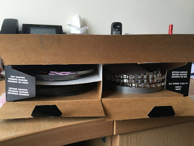
Next, gapping the rings. It took me quite a while of searching and reading before I was certain which ring was the top ring and which was the second. The top rings (in my set - Sealed Power) have a shiney outer diameter and the second are all cast iron grey. They are colour coded but no info was given to the coding! Both have assembly marks to orient top on assembly. The mark on the second ring is incredibly small. Whilst gapping them I made sure that each was in its correct bore, correct orientation and totally parallel with the engine deck but about a cm below the surface. Filing by hand is a slow and painful process (my thumb is still numb after 3 days!).

Complete set of Sealed Power (Federal Mogul) 4.03" Piston rings.
Top LH support rings, 
top middle & top RH - Oil rings, lower LH - second rings, lower RH - top rings,  

Top ring identification mark
Second ring identification mark. Can you see it!


Recommended gaps are as follows:-
Top ring 0.016" - 0.018";
Second ring 0.020" - 0.022";
Oil rings 0.015" - 0.055";

The oil rings didn't need filing as they were all within tolerance.

One word of warning!!!! Be absoultely certian you don't have 2 feeler gauges stuck together when checking the gaps. I did on ring 15 out of 16 and it cost me a new set of rings!!


The new box of piston rings have arrived this morning so I can complete the gapping now (when I find a little time). Just got loads of spare rings that hopefully I won't need. One thing to note is that all rings are all very clearly marked on the box. I completely missed this first time round. At least what I found on the search ties in with info on the box.


Next was piston assembly (less rings). This entailed cleaning everything throughly again and getting clear in my mind the corect orientation of postons and con-rods. That sorted I began  with cylinders 1 thro 4 as the orientation of the pistons and rods are the same for each bank of four.

On the con-rods there are 2 chamfers where the bearing shells fit. The larger chamfer fits, or rather clears the large radius on the crank journal else the con-rods will not fit!

My pistons have full floating pins which have coiled wire locking rings. These are a complete pain to fit. I've lost count of the little cuts and scratches I got when putting these in. You have to 'stretch' them before you start, feed the first loop into the groove and slowly push the rest into the groove with a small flat screwdriver. There is a real knack to this and it got very much easier after the first dozen or so!!.


Lastly (at least for now) came the assembly of the rings onto the pistons. At this point every piston became bore specific and it is essential to keep them all carefully numbered so that the right piston/ring assembly goes in the correct bore. I numbered the box the pistons came in to make indetification easier when I come to assemble them into the block.


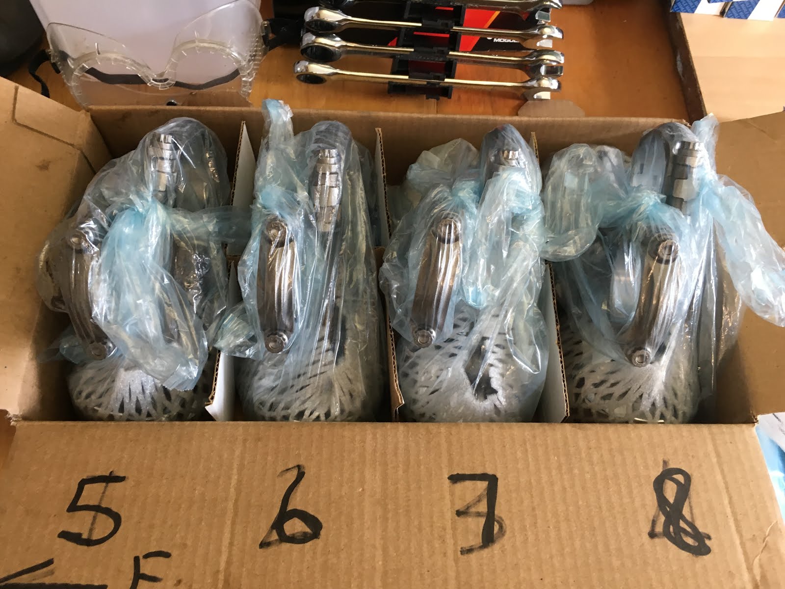
Cleaned, oiled, assembled, bagged and boxed awaiting final assembly into the block. I attemped the first piston assembly into the block at the weekend but gave up pretty much instantly as the rubbish ring compressor from good old eBay gashed my hang so it went in the bin. I have a 'tapered sleeve' ono order from Stateside Autos in Nuneaton. Should be here on the 23rd all going well. So that is about it for now.

And yes I got the numbers on the box the wrong way round!


Wednesday 3 August 2016

Engine - Pt 3

OK then, finally made a start on the engine build. Loads of reading and preparation before starting as this is not something I do on a regular basis.

First thing to do was very thoroughly re-clean the block with particular attention to the oil galleries. I got a set of gallery brushes from Stateside Autos and used loads of brake/clutch cleaner to make sure that all was good. Essentially we are starting here with a nice clean painted block.


As I am 'stroking' the engine from 302 to 347 I have to make sure that the rod bolts all clear the piston bore skirts (and anything else as well). I assembled the crank one piston/rod assembly and began methodically to check where the issues are. These were all marked in green for removal shortly. This was all then re-checked just to make sure.

The next stage had me sweating buckets as I really didn't want to slip and gouge a bore!!. I proceeded very slowly at all 8 areas first using the die grinder following with the Dremel and a sanding drum to remove all sharp areas and corners. The result is what I hoped for in that all are now well clear so no more interferences.

Shows interference for cylinder 1
Area to be removed at cylinder 5


Now ground and polished
Cleaned thoroughly and then each cylinder was checked


There was a awful lot of cleaning after the grinding and polishing. Then some more!!

Next came the core plugs. These had sealant applied around their edges before placing in the holes in the block. Each was hammered home using a suitable size socket. All seated just below the chamfer. After this all excess sealant was cleaned off.

Shows interference for cylinder 1
Area to be removed at cylinder 5


Next came the oil gallery plugs. These were all drilled and tapped to take socket grub screws. As before these had sealant applied before inserting and tightening up.


This just leaves the gallery plugs and the camshaft cover but I will have to take the block off of the stand to do this which is a bit of a pain so will do that when I next have a few hours spare. So it is all bagged up and sealed for now to keep it clean for later.

Monday 1 August 2016

Handbrake Mech - Pt 4

Secondly I have made and fitted a small plate to fully secure the modified handbrake cable to the chassis. I have never been happy with relying on purely the tension of the cable to keep it in its location so a small 3mm thick stainless plate has been added.


Still got to weld in the small tube to take the other end of the cable but I will do that a little later.

Off to night school to learn how to MIG weld!

Fuel line - Pt 3

At the end of last week I tidied up a few things that were not complete before I start the engine build in anger.

Firstly I have now finished fitting the fuel pipe run having replaced the connection to the filter with APS fitting which means it will be easier to replace the filter in due course. I got a few marks on the nice annodised parts but these should be OK.


All that now needs to be done is to cut to length but this will be done when the engine is installed.


Bell Housing

I purchased an aluminium bell housing to suit a Ford SMB 302 to Tremec TKO600 from Roadcraft last year. As soon as I got it I was really concerned with the surface finish of the casting. It looks like it is seriously cracked in many places. I had a good chat with Brian at Roadcraft (who has been absoultely brilliant I must add, can't speak more highly of him or Roadcraft as a supplier) who agreed to replace it with the best one could find from his next batch from Tremec. It was exactly the same as the one I had already received. It now looks like the die tooling for the casting has many surface cracks in it and these transfer onto the cast part which gives the 'appearance' of cracking.

Surface defects on the bell housing
Being a bit sad I did not want to leave my bell housing looking like this so I spend an evening smoothing out all the (or at least as many as I could get at!) imperfections which left a very much more ascetically pleasing apperance although it would not stay shiny for long if left uncoated. I decided to have it powder coated in red, RAL 3030 to be precise and I must say that it now looks really good. 

After coating. All smooth and shiney....
At a cost of only £40 I am well pleased. I took it to Rugby Power Coatings. After masking all the machined areas and plugging all the tapped holes they had it media blasted to provide a good key for the powder coat. They undercoated it first with a zinc rich primer as this can aid in creating a better bond but also creates a thicker smoother overal finish on the coated parts.

Tuesday 12 July 2016

Handbrake Mech - Pt 3

I finally found the time to start looking at the mod to the chassis to fit the 'pulley' setup for the revised handbrake mechanism. I was a bit concerned about drilling trhough the plate as the position is a bit tight to get at. I had no need to worry as all went really well from the start.

I carefully covered everything that I didn't want to be covered with swarf and then started to drill a pilot hole of 4mm As soon as it was a couple of millimeters deep I carefully rotated the drill to the correct angle to line up with the groove in the pulley and completed the hole.

This was then followed with a 20mm diameter hole saw which had its own pilot of 8mm diameter. As before i started the drill and after a few mm aligned it with the 4mm pilot hole. This made getting it all aligned a little easier. I had to be very careful as the hole saw started to cut into the plate as it was just a one sided cut so all had to progress slowly and carefully. The hole saw atr through the chassis plate much better than hoped and I have ended up with a pretty tight hole for the adapter tube.

Next I had to cut the slot for the cable. This was a labouious job and painfully slow. I ended up chain drilling a 4mm hole and using the drill as a slot drill to join all the holes up. Filing the slot was also really slow as access is tricky. Still got a little to do to make all smooth and straight (I'm a bit OCD as all has to be true and straight!).

Template added to chassis. Looks tight!!!
Drilling with the 20mm diameter hole saw. All covered.
Hole completed.
Slot added. Now just to angle and clean up.

Only thing's to do now is to weld in the adapter, clean up and repaint the whole area.

On the whole I am really pleased with the progress, just need to get that welder!!!