Wednesday 25 May 2016

Brake & Clutch pipes - Pt 4

Well I had some time last weekend to complete the brake pipes and start looking at the fuel pipe run.

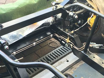
I'm pretty happy with the overall result of the brake and clutch pipes with just the short runs to the master cylinders left to do but that will happen later when I trial fit the pedal box etc. I'll probably just create a simple mock up to allow the fitting of the pedal box as others have done in the past. Must get a good supply of Dot 4 brake fluid for flushing and testing. I've added a few more pictures below of the runs that are completed.

The first photo show the need to tap the diff mount plate for the tee and then also for the p-clip that secures the nearside rear brake pipe (although this pipe may need to be re-done when I fit the fuel pipe as they will cross at some point!). The second photo shows what has proven to be an invaluable tool in drilling holes in very narrow places. this is a "Faithfull CHUCKRA Right Angled Keyless Drill Chuck 3/8-inch" that I got from Amazon.

For the pipe runs I am  generally using M5 stainless socket button head fasteners into rivnut's rather than simply tapping the chassis. I will change these to plated high grade steel as the socket is a little suspect on the stainless ones (ordered but in the post!). Before the rivnut's are swaged I've been using cavity wax just in case moisture gets inside the chassis rails now that they are drilled. All fasteners have thread lock and spring washers! Don't want them coming loose do we.

The last photos simply show the rear end runs now completed.


The only thing that may change is the nearside rear brake pipe as the fuel pipe run will cross this. It may be that I re-run the brake pipe to allow an easier route for the fuel pipe. We'll see as things continue to progress

Tuesday 17 May 2016

Handbrake Mech - Pt 2

There has been quite a lot of talk about handbrake performance of late on the forum. AK have been listening and are in the process of updating their handbrake mechanism accordingly. There is not an awful lot of changes but they are as follows:-

1) The third handbrake cable needs its outer shortening & the clevis pin clip modifying by AK;
2) A new aluminium pulley fits where the original third cable fitted, supplied by AK;
3) An additional small tube with a slot down its length is needed. This is the new cable abutment and can be supplied by AK;
4) You need a template for the modification to the chassis for the position of the new cable abutment tube (item 3 above), supplied by AK;
5) The chassis will need a suitably sized hole (approx 24mm TBC) angled hole to suit the abutment tube. This needs to be welded to the chassis with its hole aiming at the outer edge of the grooved pulley.

Parts needed (except cable!) for the mod to the handbrake mechanism assembly.
The intention was to simply bolt the pulley to the lever arm making sure the pulley is still free to rotate although not slack. Personally I don't like reamed diameters running on a threads. This all being under load and will wear the hole. Probably be OK but I have chosen to use a 10.9 grade 8mm diameter shoulder bolt as this has a nice ground diameter and the nut on the end (M6 in this case), can be tightened up hard onto the shoulder. With a spacer or two the pulley is free to spin. I must admit that I had intended for the shoulder bolt to be rigid but basically I made a mistake! I had intended to buy the next size up (10mm diameter) but got the size that fitted the pulley. This meant that I would have had to ream the pulley out to 10mm diameter. I will see how the current set-up works and decide later (before the body is permanently fitted) if this needs to change.

For info the shoulder bolt size I used is 8mm diameter with a 16mm shoulder length. With a suitable spacer this fits really well. I did have to ream the hole in the lever arm as this was a little small but better to have to make bigger than being already too big!

Pulley test fitted. Not certain if above or below is better but initially below seems to line up with the
cable anchor point pretty well keeping the cable as straight as possible (apart from around the pulley!)
Hole and slot to be cut into the chassis with the small tube to be welded here after.
As I progress I will add more info and pictures. I feel this modification will make a very real improvement to the handbrake function. Something to do with levers and pulleys!

I understand from Jon at AK that they are also looking into a 'more flexible' cable to allow it to bend around the pulley more easily. Maybe another purchase will be necessary! Time will tell.

Monday 16 May 2016

Brake & Clutch pipes - Pt 3

I had a bit more time late Friday evening and Saturday afternoon so I popped out the the garage and continued with the brake and clutch lines. As I have said before I am a little bit particular in the over all appearance I want to achieve. For all of the 'tricky' bends I do a trial to see exactly what needs to be done. That means that I only waste a small amount of pipe rather than a much longer length, although even when I do this you have to be absolutely certain which way you make the bend else you start again regardless. As they say measure twice cut once. Wish I listen to my own advise a little more!

Still, after all this I am now making pretty reasonable progress and overall I am happy with the outcome so far. Just one area not quite as I wanted but this will be staying (at least for now!).

When I came to roll the chassis out a bit so I could work on the front end area I couldn't move it. Looks like one of the slave wheels has a puncture. After re-inflating it I was able to continue but will have to rectify that later.

Progress so far is as below.

Front nearside brake and clutch pipes
Installed


All that remains now is to add a bulkhead fitting to suit the flexible hose that goes to the clutch slave cylinder, fasten the clutch pipe approximately every 250mm (must be no more than 300mm for IVA), finish the last few bends for the rear brake pipe along the chassis rail and fasten the rear brake pipes to the chassis.

The Gen III chassis is a little more fiddly getting the pipes around the new tubular sections along either side of the transmission. It was a really good job I marked where the body sat on the chassis before I removed it as I can keep the pipe clear of the body area, Marking this out before the body is removed is pretty much essential well it certainly helps with the nerves.

When all is complete I will add a few more pictures of the finished runs so you can see where it all went. Hopefully all will be OK.

Tuesday 10 May 2016

Brake & Clutch pipes - Pt 2

The next phase was to mount the bulkhead fittings for the two brake lines and clutch line. I realise that this means that there is an additional connection in each of the lines but it does mean that I will have much shorter lines to run to the master cylinders of each.

I carefully measured where I wanted the bracket to fit on the chassis and how I wanted the bulkhead fittings to mount in the bracket. This was then modeled up on CAD (just my day job!) from where I was able to get a flat pattern of the bracket. I should have had this laser cut but already had some 1.2mm thick stainless sheet so decided to cut this out by hand. It worked out pretty well. I was able to spray mount the paper pattern onto the sheet and cut/file to shape then drill all the holes, fold to shape and spend ages de-burring and finally give is a once over (maybe twice!) with a scotchbrite pad.


Did a quick trial fit of the fittings into the bracket. All seems OK so now to fit to the bracket in place on the chassis.


The bracket was clamped in position and then the chassis was drilled through the holes in the bracket. At this point I meant to squirt cavity sealing wax into the open chassis tube but basically got carried away with the pop riveter and forgot. Too late now. I used 3mm stainless pop rivets to fasten the bracket. The VIN number should still be readable after the three pipes are fitted in position but I will take a few photos for reference just in case.

Bracket in finally fitted
Bulkhead fittings all installed
I can now go on to complete the rest of the pipes.

Monday 9 May 2016

It rolls! (with a push!)

At last I feel a bit of a milestone (for me at least) has been reached. I have been able to attach the track-rod ends after first adjusting to suit the recommendations in the AK manual of 47.5" between ball centers. The manual quoted 14 turns of the track-rod ends as a good starting point. To achieve 47.5" I had to go to 16 turns. Obviously the tracking will be properly sorted later down the line (must add that to the to-do list!).

After this I covered the brake calipers with cardboard so that I didn't chip them (again!!!) when I put on the slave wheels.

After this all the axle stands were removed and it now sits proudly on its own 4 wheels. Very happy indeed. It no longer feels just like a pile of bits.

Sorry about the photo but I had to quickly take one as it started to rain so it was going back in the garage before it got all wet. A bit of an apology to my wife as the washing got left out for a bit longer than ideal but I had to get my priorities right didn't I?