Thursday 21 January 2016

Body support frame

I have had a couple of emails regarding how I made the frame on which I have mounted the body. For those that are interested I have added some more info below.

It started with a trip to AK early last year so I could see exactly what they do to move/support their bodies in the factory. I tool a few photos and some measurements and started from there.
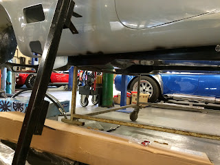
The pictures above show the AK frame and how the body sits on it. Unfortunately, even though I used the "measure twice cut once" rule my frame didn't quite come out how I wanted it but it is OK and does the job fine. I just needed to add in a few packers and supports here and there.

Basically I made the frame from some wood battening 63mmx36mm(2.5"x1.5" planed) approx. 2.4m long. I got this from B&Q for around £2.50/length. The castors all came from Machine Mart. The frame is glued and screwed throughout having first made sub-assemblies for the front and rear supports then adding the sides to complete the frame. All areas were then to be braced to make a very rigid frame that can easily be moved around the workshop or outside when necessary for complete access to the chassis for things like brake and fuel line plumbing and engine/transmission installation etc.

I started by modelling up the assembly on CAD in my 'spare time' to make sure I knew exactly what I needed. Created a cutting list from this, cut all the parts and then started assembling. It took a couple of weekends to complete, a lot faster than expected. Each different length is shown in a different colour on the CAD layout.


From here I created several drawings to help me build and get the pieces in the correct positions. First is a general layout showing various views and overall sizes, less castors. Secondly there is an overall isometric view showing the parts that connect the front and rear frames & complete the wooden structure. Lastly are the two sub-assemblies for the front and rear frames. Each drawing has a cutting list for the lengths of each part.


Below is a photo of all the parts cut and ready for assembly. I used M8 coach bolts and wood glue to permanently fix. I could have just bolted it but felt that this would not be rigid enough and with the body sitting on this for a year or so and being moved about a lot I wanted to make sure that it would stand the test of time.


I wanted the frame to be quite wide so that it would pass over a rolling chassis width. This appears to be OK at the moment but it may be different for yours. I have added a few photos of the completed frame with the body in situ.

It was essential to ensure that the timber purchased was as straight as possible. Also during construction I constantly checked that all parts were square and true to each other else this would make the joining of the front and rear frames much more difficult.

Not sure what to do with it after I have finished with it though. Hopefully it will either be near to November 5th or there's always the possibility that it would be available if someone else has need of it. I will decide later and post on the Cobra Club.com forum nearer the time.

Now for the disclaimer bit. This was designed solely for my purposes. If you choose to have a go I am happy to assist in any way I can (time affording!) but please check all the dimensions before cutting. I found this to my annoyance on more than one occasion.

If you want to contact me please do so via http://www.cobraclub.com my user name is stu238.

Tuesday 19 January 2016

Differential - Pt 3


I have now attempted to fit the diff assembly. I realised pretty quickly that there was a slight interference between the chassis and the diff body around the 2 upper fixings and also there was a larger gap (approx. 7mm) between the diff and the chassis than was expected. I had a chat with AK and they confirmed that this was to be expected depending on which diff you fit. Obviously mine was not the one that the chassis was specifically designed for so a little bit of grinding was performed and additional spacers were purchased.

Great!!! Seems to be a small foul at the top and a bit more gap between the diff and the mount point as well.
The photo above shows the template and the photo to the right shows the foul. No major worries though. Quickly sorted with an angle grinder s splash of paint.

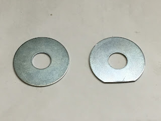
To enable the spacer washers to fit correctly into the machined cut-out on the back of the diff a little modification needed. These all now fit really well. I had to purchase a couple of different grades of washer to get the different thicknesses to get to the 7mm thickness I needed.


I finally thought that I had got the diff sorted. I added the nuts and washers and began tightening to the correct torque. Very quickly it became apparent that the four studs around the diff nose were too short! No option but to remove the diff and unscrew the studs a few more threads, I'd simply screwed them in too far. Another very important note is that you cannot use stainless nylock's. They simple can't take the torque needed. As I was tightening one of them I realised that it was not getting tighter so removed the nut and could see deformation of the thread. No option but to buy some more Grade 8.8 nuts and discard any stainless ones sitting around.
Diff finally installed. Just need to check the torque of each nut and then paint spot each when OK.
Oil now added, 2.1 litres of LSD oil as recommended. Just to the lip of the drain hole.

Wednesday 6 January 2016

Body/Chassis Delivery

This post is a rather late and out of sequence I'm afraid. Took all the photos but got side tracked somewhat. Still better late that never.

After great anticipation the day finally arrived for the delivery of the body/chassis kit, 31st July 2015. I was so relieved to wake up that morning and see the sun shining. It could not have been a better day. For me it was the culmination of a 30 year ambition back from the days of the LR Roadsters RAM Cobra, Southern Roadcraft and the like. Things have moved on quite considerably from those days.

All is revealed. What a lovely site!
As you can see I have opted for twin roll hoops and twin fuel fillers. I do like all things symmetrical. I have opted not to have the 3 front air scoops as for me these detract from the beautiful lines of the body. Each to their own though.


 The week before delivery I was really busy in building a wooden frame for the for the body to live on. This would mean that the body would stand over the chassis and I could leave it safe and secure in the garage but still be able to move it out of the was when necessary.
The body now seated on its frame. Needs a little positioning but should be good.
Chassis positioned in the middle of the floor area. This will be static until the wheels are added.
Finally all safely stored.
I would really like to thank all those who helped lifting and sorting, you know who you are. I could not have done it without any of you.

Tuesday 5 January 2016

Power Steering Pump - Pt 1

I have opted to go down the electric power steering pump route. I was advised by Jon to look for a Citroen Saxo pump which I found at a local breakers. It came in at £25 so not too bad. It came with all its brackets, pipes and remote reservoir although I may well change this for a new one later.

As received from the breakers
Part dismantled but clean
Fully re-furbished and ready to fit.
The pump still needs a new connector, pipes and modification to the mounting bracket. This will all be sorted out a little later in the build process.

Front Suspension

Finally got round to starting the front suspension build along with the anti roll bar fitting.

Following the instructions for the Gen II manual worked pretty smoothly although cleaning out several of the suspension pivot holes caused a few issues.

With both top and bottom wishbones installed the chassis was carefully trued up to allow for accurate setup of the camber and caster angles. Essential to read carefully the manual and proceed slowly, one side at a time.

Setting the caster between 6 to 8 degrees

Front coil over shock added with the anti roll bar mount just being drilled and tapped. Drilled through at the front and tapped at the rear.

 Nearside complete apart from brake calipers and attachment of track-rod ends. The disc's are yet to have the protective coating removed but this will be done when the calipers are finally fitted.

Offside complete apart from brake calipers and attachment of track-rod ends.

Differential - Pt 2


Both output shafts have now been fully re-furbished with a new seal, bearing and bearing collar. Liquid nitrogen was used to freeze the shafts whilst the bearing collars were heated meaning that the collars could then be simply dropped in place and held in position whilst the temperatures stabilised. Thanks to Craig for all his help in this and other areas.

Seal insertion tool along side the new seal.

New seal correctly inserted


Side shafts are now installed after measuring the gap between the bearing housing the diff body to ensure that the bearings are held secure upon tightening the 5 screws on the bearing housings. Don't forget to add the seal after measuring.
 
The diff now completely re-furbished and re-assembled. Mustn't forget to add the oil though!

The weight of the differential was a bit of a problem and I was concerned about holding it securely and level whilst I was still able to manoeuvre it around during installation. I used a couple of fridge skates screwed to a handy piece of chipboard and then built it up to approximately the correct height to suit the chassis (as I have it on stands). I can then raise/lower the chassis to get the diff installed. This meant that there was little heavy lifting involved.


I have had to stop there due to time constraints but will update more as time affords.