Monday, 23 July 2018

Front mesh - Pt 1

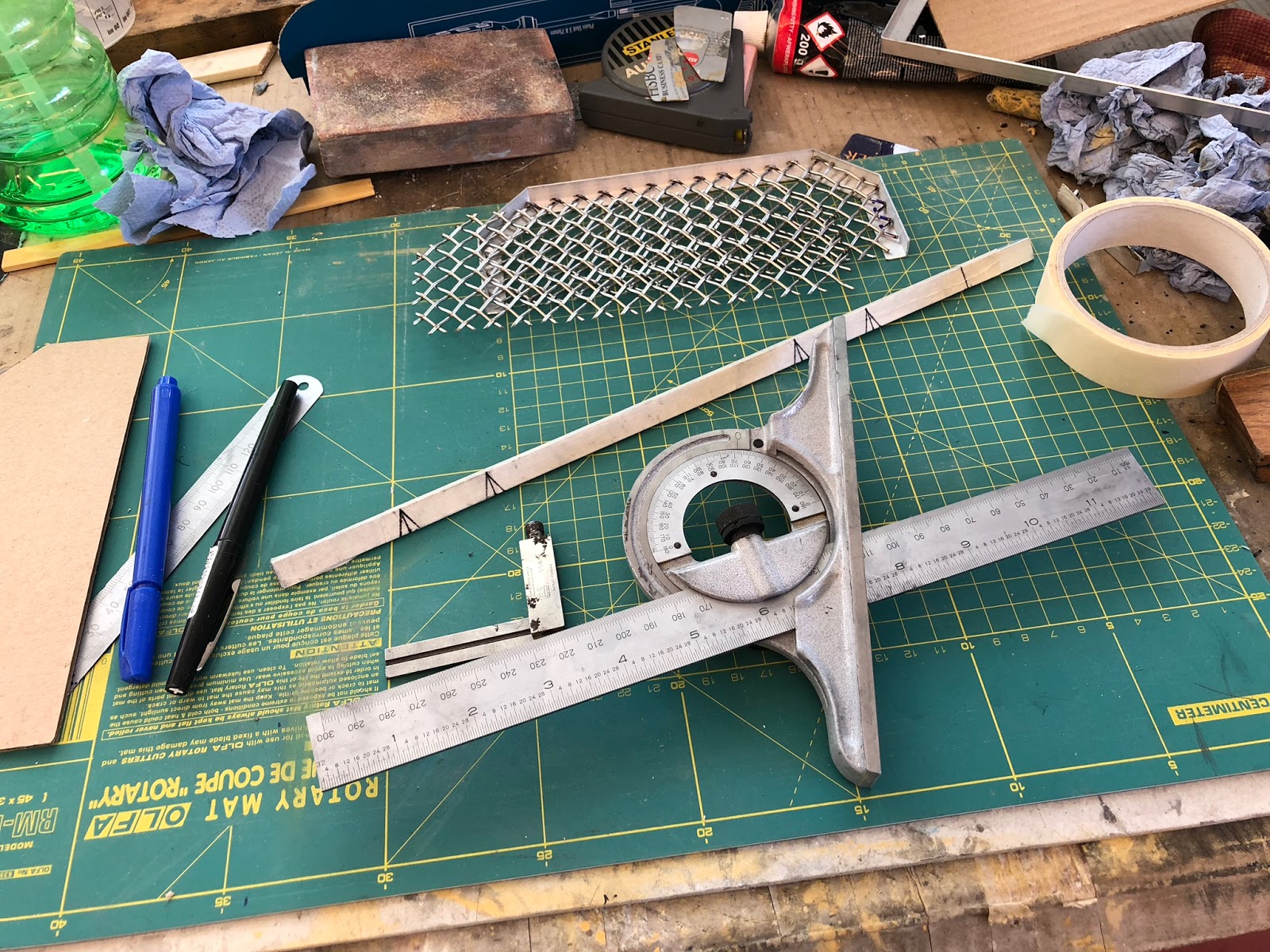
While I was waiting for the offset dowels to arrive following dial-in of the bell housing I thought I would have a go at the front mesh grills. Don't want the front all filled in with mesh but just the one below the rad opening and the two smaller ones either side.

I purchases some of the Eastwood electro-polished mesh and they cut it to size for me. All I had to do was cut off the corners and make a suitable frame to carry it and fix it to the body.

I started with the one below the rad/cooler. Cut the corners off the blank that was supplied and cut and formed a small aluminium frame to carry the mesh. This could then be either bonded or bolted to the body (TBC).


I then moved onto the two side grills. These have a 3 sided frame but seem to be OK.


After the frames were completed that were all sprayed black and then the mesh was bonded to the frame using black Tiger seal.


The lower grill test fitted in its aperture. I'm really pleased with how it looks.


Monday, 18 June 2018

Lights - Pt 1

Thought I would take a break from sanding and filling of the reverse and fog light moulds. Time to look at fitting the rest of the lights front and rear so I started with the headlights. First thing to do was sort out the centre on the mount area's, sand flat and then mark out.


This proved to be relatively straight forward I'm pleased to say so I used the same process for both sides. Only really needed a little flattening over mound/split lines and the hole (already cut) needed a little bit of sanding to make round and uniform thickness.


Just had to make sure that I had the bowls up the right way. I carefully marked all the holes, piloted them and carefully drilled them with a step drill till the right size was sorted. I fastened them all with pan head cap screws, large washers and nyloc nuts. The RH photo shows the template I made for sorting the position of the indicators. I was able to cover the area on the body with masking tape and spot through the template. After this holes were cut carefully with either a stepped drill or a hole saw used with very gentle pressure.


First side light fitted. Still need to change the bulb for a mirrored style.


Front all done for now. Now onto the back.

As before I have made a template for how I want to position the lights so, after applying masking tape in the offending areas, this was careful positioned and all holes spotted through onto the tape.


There is a slight issue with the moulding on the offside as it will need a little building up for the light to fit as I want it.


So for now that's all I'm doing with the lights. Its starting to look more like a car at last.

Fog & Reverse Lights - Pt 2

Both solid plugs are ready to bond to the rear valance sections and then fill, sand, fill, sand ........ until perfect.

First one with the first coats of primer ready for final filling as I can now see the small areas that need a little work.


I'm going to fix this to a thick strong base to remove the flex from the fibre glass part. Still got a way to go but should be OK. Just got the cover to create for inside the boot but I will do that after these are fitted into the body.

Mmmm! A bit of a of warning needed here. Make sure your paints are compatible else this happen's! Lots more sanding now required. Don't make my mistake.


Oh well, practice is good. So, after much more time I am to the stage below and all is OK. Just need to fill a couple of small areas on the LH one and finish sand the other and then I will gloss and wax ready for moulding.


Saturday, 19 May 2018

Brake & Clutch pipes - Pt 6

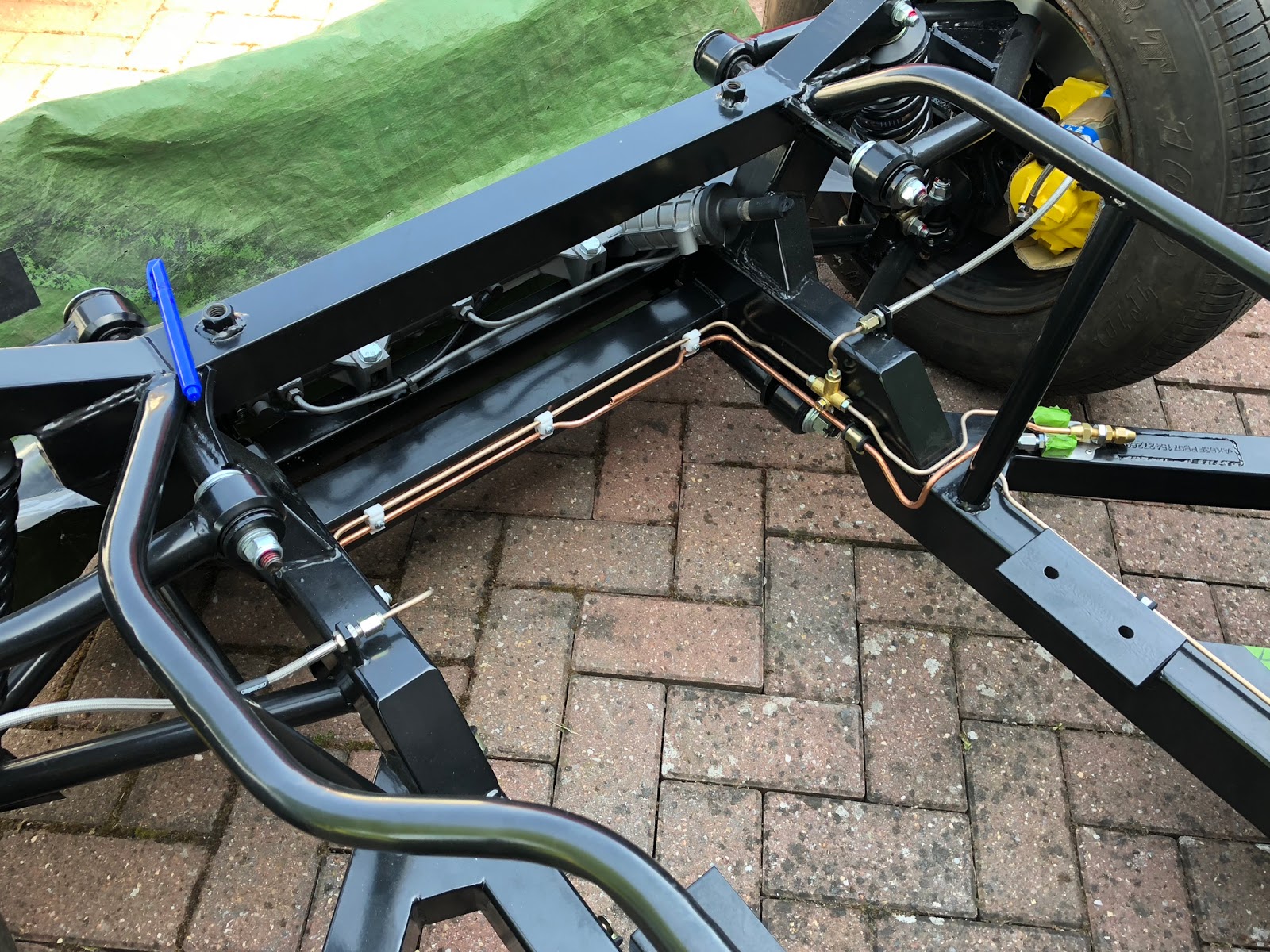
When going round the AK stank last year I noticed that the clutch pipe appeared larger than the brake pipes. I have taken quite a lot of time in getting the pipes exactly how I wanted them so was a little concerned when I saw this. Off I  went to have a chat with Jon and he explained that it would be much better to have larger pipe for the clutch else the pedal pressure may be higher than I would really like. That was a bit disappointing I must say!!!

Oh well, nothing for it. I have to change from 3/16" up to 1/4" pipe. My biggest concern were the small stainless bracket I had fabricated and riveted to the chassis rail and the plastic clips that are holding the pipe on its routing as I didn't want to have to drill loads more holes for additional clips.

I decided to go for copper this time. I did have quite a difficulty in getting the fittings though but eventually found what I needed. Also I decided to split the pipe into two to make it much more manageable when forming and fitting (not to mention there would be less waste when I bend it the wrong way!)

Well lets get started....

First this to do was remove the old clutch pipe. The plastic clips are really rather 'grippy' and it was a bit of a struggle in getting the old pipe out. Good job it was being replaced! Anyway, I persevered and out it came. I also had to take off all the clips as these were only for 3/16" pipe but fortunately I was able to easily modify these at accommodate 1/4" too to that was a relief.

New 7/16" bulkhead fitting.

I had to tap the bracket 7/16" UNC else the hole would have been too big for the material left making it weaker than I want.

Now for the 'fun' part. Straightening the pipe is easy with the pipe straightener but I had to get another one for 1/4" pipe. I couldn't quite get the same run as originally so had to lift it up a little to clear the brake pipes.

First half straightened, cut to length and bent as necessary.

Copper, even a little larger in diameter is easier to bend that the cunifer I used for the brake pipes. I'm happy with the result and the pipes don't touch either where they cross over. It also makes it better when forming the swage on the pipe ends too.


I had to wait a few days for the straight connector to arrive but now it is here and fitted I'm pleased with the result. Just got a few clips to sort and then that leaves the connection to the clutch actuation on the bell housing but that will be a flexible hose.


Now the M5 rivnuts have arrived I can complete the fixings for the section that goes to the clutch.


Rear section fully fastened. Just connection for flexible to add.

Wednesday, 16 May 2018

Engine - Pt 11

Moving on from last time we are coming towards the end of this engine build. Now I want to try and get the front of the engine completed as much as I can before testing.

Coil Mounting.
I have had a nice bracket made to mount the coil on the front of the LH (view in car line) cylinder head. This has been anodised black and I have used stainless fasteners in keeping with the rest of the build (more or less). The photo below shows the bracket and some of the spacers that have been used to alight the pulleys and the alternator.


Front pulley spacer and fasteners

Front pulley spacer
Front pulley fitted

After sorting front end auxiliary drive
Spark Plug Cables.
I purchased all the necessary parts from Summit Racing. 25ft reel of 8.5mm diameter cable, plug caps and, a distributor set caps and a set of crimping pliers. All the connectors are of the double crimp variety.


I'm intending keeping them all tidy with a nice milled and polished billet aluminium bracket. It didn't take too long to sort the cables and tidying up on each side. As each cable was prepared I added the cable identification tag.

1-4 sorted just 5-8 to go!

I must say that I am really happy with the overall look, however I have realised that the alternator will have to move due to chassis rails and this may also affect the cable mount brackets. Oh well, if it does I'll sort something else.

Fuel Pipe.
The next item I've added is the braided hose for the feed from the fuel pump to the carburettor. The only thing that took a little time was having to make up a suitable stainless bracket to guide the hose where I wanted it to go.


Still need to tidy the cables and get a couple of clips else ready for testing. Just need to add the frame I welded up for transportation etc.


Just got a few holes to plug and tape over and then it is off to Peter Knight Racing.


So.... That's it then. All delivered to Peter Knight Racing waiting for setup and run-in and dyno. Lets see how it performs. Should know in a week or so. Feel rather nervous but there is nothing more I can do now.

Fog & Reverse Lights - Pt 1

Now for something a little different than engine work. I am one of those people who like things all smooth so naturally I am going to french in both the reversing light and rear fog light.

I had to find a standard automotive light that was suitable and found those on the BMW Mini R50 are just right for the purpose I have in mind. There are both a reversing light and a rear fog light that fit very nicely into the rear bumper of the Mini. All I have to do is replicate the hole for the lights and bob's your uncle! (hopefully!!!)

Now for the parts. I purchased both rear lights and part of each loom (to get the correct connectors) and a scrap R50 rear bumper with the hole needed. These are a nice little clip in lights that will fit flush with the rear valance when finished.

Portion of Mini rear bumper


Clamp bracket and fastening
The first thing that I have done is to carefully mark out where I want the lights to go. AK has very kindly marked the lights on the car so I worked around these measuring exactly where I want them to go. Finding the centre line is a bit tricky with all the curves. All centred around the boot opening but this can be adjusted a little if necessary to ensure it looks right.


I've marked out the boundary I want for each part and then done a 3-4mm chopped strand mat layup over each area having first carefully applied mould release to ensure that parts come off the body OK.


Next job was to start making the mould for the light cavity. I have had to simplify it a little so that it is mould-able but even so the first try was a complete disaster! I had decided to try with just a thin skin of fibreglass but this was a big mistake. I ended up peeling it out in several pieces and re-thinking the whole process.


I decided to make the plug from silicone and then make another silicone mould over that and finally use tooling resin to make the rigid plugs to make the proper moulds with.

Bridge over the top of the light
Small aluminium bridging piece

Bridge covered with P40 for a bit more strength
All fully enclosed and sealed up

Front of mould border complete
Silicone poured. Lots of bubbles but will be OK

Plug removed and ready to create secondary mould

Now for the next part, the outer silicone mould that will create the solid plug for the light cavity that will be bonded to the small plate that was moulded on the rear of the car.

Balsa frame ready for covering the male plug

Male and female parts ready for solid core to be made

Now its time to pour the first of two solid core's from tooling resin that will enable me to make the proper cavity moulds that will be let into the bodywork.

Ready to pour with side supports
First one done, de-mould tomorrow

That's as far as I have got with this for now so more updates later.