Monday, 11 July 2016

Engine - Pt 2

After the initial set back of the first block being cracked I got the second block back fully machined with no further issues. I had all my machining done by Dave at Dave's American Machine Shop over in Hinckley and a very good job he did too.

Dave initially measured the block to see what how it stood before machining. He then proceeded to machine the deck height and square up the head faces to the bores. The bores were then machined to +0.030" taking the bore to 4.030" and with stroked crankshaft I will now have a 347 up from a 302 as standard. After machining and honing the bores he tapped the smaller core plug holes for better sealing. Following this he chemically cleaned the block and when rinsed and dried he inserted new cam bearings. He also provided a full core plug kit for me which I will fit in due course.

When I got the block back home the first thing I did was to clean it again as I wanted to get all necessary areas painted. I've decided to paint the block in a neutral colour, that being a graphite engine enamel. This needed several sprayed coats and I am really happy with how it looks. Dave also advised me to paint the inside of the block particularly the area below the intake manifold and each end as well. This really helps with oil drain back to the sump. He uses good old Wilco red oxide primer and then follows this with a couple coats of their red tile paint. I've duly taken his advice and all looks good.

Block 2 at collection - image 1
Block 2 at collection - image 2
Midway through red oxide priming
Completed block. I'm really pleased with the result

I guess what I should have done is given you the specification (so far!) of what I am building, a bit out of order but here goes:-

  • Small block Ford 302 bored and stroked to 347;
  • Scat Series 9000 Cast Pro Comp Stroker Lightweight Crankshaft 9-302-3400-5400-2123;
  • SBF 28oz Fluidamper 6 5/8" FLU650211;
  • Scat Pro Stock I-Beam Floating Pin Connecting Rods 2-ICR5400-927;
  • Keith Black KB Performance Pistons KB246030-8;
  • Clevite main and rod bearings;
  • COMP Cams Xtreme Energy Camshaft 35-518-8;
  • Ford Racing Fuel Pump Eccentric M-6287-B302;
  • Melling Camshaft Thrust Plates MF126;
  • Lunati Street Performance Retro-Fit Hydraulic Roller Lifters 72335-16;
  • Harland Sharp Original Roller Rockers S4102 Ratio 1.6:1;
  • Cylinder heads AFR 165cc/185cc/195cc SBF Renegade 20 Degree Street/Strip 1388;
  • Pushrods will be supplied by Peter Knight Racing TBC;
  • Edelbrock Performer Carburettor 600cfm 14064;
  • Edelbrock Performer RPM Intake Manifold 71214;
  • Ford Racing Timing Chain Set M-6268-A302;
  • Edelbrock Victor Series Mechanical Water Pumps 88414;
  • MSD 6AL Ignition system MSD-6425;
  • Distributor MSD-84791;
  • Ignition coil MSD-8200;
  • ARP headstud kit ARP-254-4405;
  • ARP Main Bolt set ARP-154-5001;
  • FelPro gaskets througout;
  • Miloden oilpan MIL-31600, larger capacity same depth as standard;
  • Miloden oil pump pickup MIL-18485;
  • Melling oil pump MEL-M68;
  • Melling oil pump drive shaft MEL-IS-68;
  • Single piece rear main seal FEL-2922RS;
  • Transmission TKO600 with upgrade to McLeod RST twin plate clutch;
I'm sure that there will be more parts (no doubt I've forgotten a whole load and will need to order more!) but I will update as I progress forward.


Back to where I was....

I sent all of the rotating parts out dynamic balancing and I'm pleased to say that all went well with little work needing to be done. All in the balancing was able to be done internally (mainly on the crankshaft counter balance weights. Pistons and rods also had a little fettling as well.

All the parts ready for balancing.
The parts that went for balancing were as follows:-

  • Crankshaft;
  • Con-rods;
  • Pistons and pins (now matched);
  • Clutch assembly and bolts;
  • Flywheel and bolts;
  • Damper;
  • Piston rings, big end bearings and gudgeon pin wire locks were needed for weights;
As they say 'that's all for now' on the engine front. I'll start the engine build in earnest after the fuel pipe and handbrake mods are completed.

Tuesday, 14 June 2016

Brake & Clutch pipes - Pt 5

As mentioned in the last brake pipe post I may have to re-do one of the pipes due to the fuel pipe run. Now that I have now pretty much sorted the fuel pipe run this did indeed mean that I had to re-do the nearside rear brake pipe. This was only a short pipe and took only a short time to do but all now clears and I am happy with the result.

The new pipe runs above the fuel pipe (a short length of coper is shown clamped wheel the pipe will run)
The brake pipes are now complete apart from the short runs to the master cylinder. These will be done when the body is on maybe later this year depending how I get on with engine build and installation.

I also decided to change all of the fixings I was using to fasten the pipe clamps from stainless button head screws to grade 10.9 zinc plated button head screws. I was finding that the hex socket in the stainless ones was stripping a little to easily when trying torquing up. Rather sort now than when the car is complete and I find I can't get in there and the head strips. All fixings have spring washers and thread lock. Not only does this stop the screws from vibrating loose the threads are sealed into the chassis as well.

Saturday, 4 June 2016

Fuel line - Pt 2

Finally now I have had a little time to get back out in the garage a fit the now painted fuel pipe and fuel tank permanently (at least for now!). I spent a lot of time de-burring the connections of the tank and then attempted to get all those little bits out rather than just catching them all in the filter. After hafl an hour or so I finally gave up realising that I was just not going to be able to get them all accepting that I would have to change the filter sooner than hoped.

Forward part of the pipe
Rear connection to tank well clear of all bolts.
New nearside brake pipe formed and fitted

Now I have thought about removing/cleaning the filter I have decided to change the connection to the front of the filter. I am going to change it to an APS anodised fitting to make removal that much easier. Still need to order the parts so this will be done a little later.

Fuel line - Part 1

With the brake and clutch lines completes as far as I can for now the next thing was to start looking at is the fuel line. As far as I can see the normal route on an AK is to run it under the diff and then route it along the inner face of the nearside chassis rail (for Ford anyway) with the fuel filter as close to the rear as you can get as the transmission tunnel area widens just before the diff mounting plate.

I have seen many routings under the diff that are very well done with a suitable guard but this route has always bothered me as the fuel line is then the lowest thing under the car and there is a risk of grounding on the guard. I spent quite a while reading through various build blogs and eventually posted a question about this on the UK Cobra Club Forum recently. I got a few replies (thanks to all) and there was one who has done what I was hoping to do and this was Steve and he very kindly added photos of his route on http://stevesakcobrabuild.blogspot.com, Nov 2015. This means that the fuel pipe is then completely within the height of the chassis and pretty much fully protected (the only area on minor concern is at the fuel outlet from the tank. May still need a much smaller guard here!). I will be able to secure the pipe by using either one of the diff cover bolts or the tie bar bolt adding a small bracket and then also adjacent to the diff with a clamp on top of the chassis rail.

I've realised that this does mean however that I will have to re-do the nearside rear brake pipe but no worries, this is just a short length.

Anyway The first thing I decided to do was to sort the position of the fuel filter. This will be on a small bracket bolted to the chassis. The bracket is slightly angled to help the 'run' of the pipe.

Filter and stainless bracket
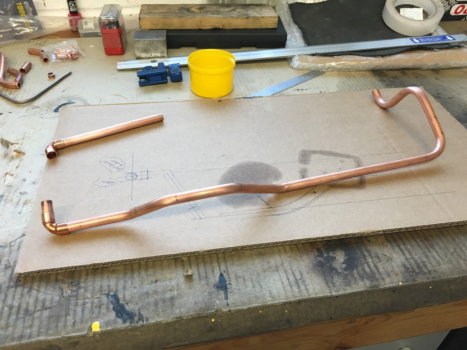
For the part from the tank to the filter I'm using 10mm copper pipe. The route is pretty tortuous but actually proved quite satisfying when all bent to shape although it took several goes to get it right (including the kinked one!! last but one bend). The copper pipe is supplied 'coiled' so has to be straightened by hand! This a slow laborious process unless you purchase yet another pipe straightener but I'm not going to spend the money on that! Hopefully I shan't need to do it again (but I did!!!)

Version 2 finished & ready for soldering so I thought!
Kinked! Last but one bend. Another opportunity!
Version 3 ready for last bits to be soldered
3mm stainless bracket to fix to tie-bar bolt
From tank past tie-bar to bracket

Under diff body well away from the drive shaft flange
Painted and ready for fitting
The pipe from the tank will be fitted when I have sorted fuel sender and when the tank is flushed and finally fitted permanently (at least that is the plan).

I have now run the braided hose from the filter up to the engine mount area. Still need to determine exactly where this needs to be fastened for the pump in my case an Edelbrock Performer RPM Street Fuel Pump 110gph mechanical unit (EDL 1725).

Braided hose run so far

Wednesday, 25 May 2016

Brake & Clutch pipes - Pt 4

Well I had some time last weekend to complete the brake pipes and start looking at the fuel pipe run.

I'm pretty happy with the overall result of the brake and clutch pipes with just the short runs to the master cylinders left to do but that will happen later when I trial fit the pedal box etc. I'll probably just create a simple mock up to allow the fitting of the pedal box as others have done in the past. Must get a good supply of Dot 4 brake fluid for flushing and testing. I've added a few more pictures below of the runs that are completed.

The first photo show the need to tap the diff mount plate for the tee and then also for the p-clip that secures the nearside rear brake pipe (although this pipe may need to be re-done when I fit the fuel pipe as they will cross at some point!). The second photo shows what has proven to be an invaluable tool in drilling holes in very narrow places. this is a "Faithfull CHUCKRA Right Angled Keyless Drill Chuck 3/8-inch" that I got from Amazon.

For the pipe runs I am  generally using M5 stainless socket button head fasteners into rivnut's rather than simply tapping the chassis. I will change these to plated high grade steel as the socket is a little suspect on the stainless ones (ordered but in the post!). Before the rivnut's are swaged I've been using cavity wax just in case moisture gets inside the chassis rails now that they are drilled. All fasteners have thread lock and spring washers! Don't want them coming loose do we.

The last photos simply show the rear end runs now completed.


The only thing that may change is the nearside rear brake pipe as the fuel pipe run will cross this. It may be that I re-run the brake pipe to allow an easier route for the fuel pipe. We'll see as things continue to progress

Tuesday, 17 May 2016

Handbrake Mech - Pt 2

There has been quite a lot of talk about handbrake performance of late on the forum. AK have been listening and are in the process of updating their handbrake mechanism accordingly. There is not an awful lot of changes but they are as follows:-

1) The third handbrake cable needs its outer shortening & the clevis pin clip modifying by AK;
2) A new aluminium pulley fits where the original third cable fitted, supplied by AK;
3) An additional small tube with a slot down its length is needed. This is the new cable abutment and can be supplied by AK;
4) You need a template for the modification to the chassis for the position of the new cable abutment tube (item 3 above), supplied by AK;
5) The chassis will need a suitably sized hole (approx 24mm TBC) angled hole to suit the abutment tube. This needs to be welded to the chassis with its hole aiming at the outer edge of the grooved pulley.

Parts needed (except cable!) for the mod to the handbrake mechanism assembly.
The intention was to simply bolt the pulley to the lever arm making sure the pulley is still free to rotate although not slack. Personally I don't like reamed diameters running on a threads. This all being under load and will wear the hole. Probably be OK but I have chosen to use a 10.9 grade 8mm diameter shoulder bolt as this has a nice ground diameter and the nut on the end (M6 in this case), can be tightened up hard onto the shoulder. With a spacer or two the pulley is free to spin. I must admit that I had intended for the shoulder bolt to be rigid but basically I made a mistake! I had intended to buy the next size up (10mm diameter) but got the size that fitted the pulley. This meant that I would have had to ream the pulley out to 10mm diameter. I will see how the current set-up works and decide later (before the body is permanently fitted) if this needs to change.

For info the shoulder bolt size I used is 8mm diameter with a 16mm shoulder length. With a suitable spacer this fits really well. I did have to ream the hole in the lever arm as this was a little small but better to have to make bigger than being already too big!

Pulley test fitted. Not certain if above or below is better but initially below seems to line up with the
cable anchor point pretty well keeping the cable as straight as possible (apart from around the pulley!)
Hole and slot to be cut into the chassis with the small tube to be welded here after.
As I progress I will add more info and pictures. I feel this modification will make a very real improvement to the handbrake function. Something to do with levers and pulleys!

I understand from Jon at AK that they are also looking into a 'more flexible' cable to allow it to bend around the pulley more easily. Maybe another purchase will be necessary! Time will tell.

Monday, 16 May 2016

Brake & Clutch pipes - Pt 3

I had a bit more time late Friday evening and Saturday afternoon so I popped out the the garage and continued with the brake and clutch lines. As I have said before I am a little bit particular in the over all appearance I want to achieve. For all of the 'tricky' bends I do a trial to see exactly what needs to be done. That means that I only waste a small amount of pipe rather than a much longer length, although even when I do this you have to be absolutely certain which way you make the bend else you start again regardless. As they say measure twice cut once. Wish I listen to my own advise a little more!

Still, after all this I am now making pretty reasonable progress and overall I am happy with the outcome so far. Just one area not quite as I wanted but this will be staying (at least for now!).

When I came to roll the chassis out a bit so I could work on the front end area I couldn't move it. Looks like one of the slave wheels has a puncture. After re-inflating it I was able to continue but will have to rectify that later.

Progress so far is as below.

Front nearside brake and clutch pipes
Installed


All that remains now is to add a bulkhead fitting to suit the flexible hose that goes to the clutch slave cylinder, fasten the clutch pipe approximately every 250mm (must be no more than 300mm for IVA), finish the last few bends for the rear brake pipe along the chassis rail and fasten the rear brake pipes to the chassis.

The Gen III chassis is a little more fiddly getting the pipes around the new tubular sections along either side of the transmission. It was a really good job I marked where the body sat on the chassis before I removed it as I can keep the pipe clear of the body area, Marking this out before the body is removed is pretty much essential well it certainly helps with the nerves.

When all is complete I will add a few more pictures of the finished runs so you can see where it all went. Hopefully all will be OK.