Tuesday, 21 August 2018

Heater Control Box - Pt 1

I have it on good authority that I must have air capable of being directed to the feet and screen (bosses requirement!). Also heated seats! Still, this is about the air box.

I could have gone down the normal route of using the fibre glass cover etc but wanted to do something a little different.

I spent some time working  out what size I wanted etc and then came up with the design (normal belt and braces stuff) that I was happy with.

As is normal for me I sat down behind my CAD screen and had a bit of a dabble.

Outside of new heater box
Inside of new heater box
Laser layout with all parts unfolded
Now for the next phase, manufacture. I have chosen to have all the parts laser cut in 1.5mm thick aluminium sheet by a local company in Coventry. They have done a great job and it only took a few days to complete.

The parts as they arived
Obviously I have to get a number of other parts but most of those are sourced from eBay. Now to the making of it.

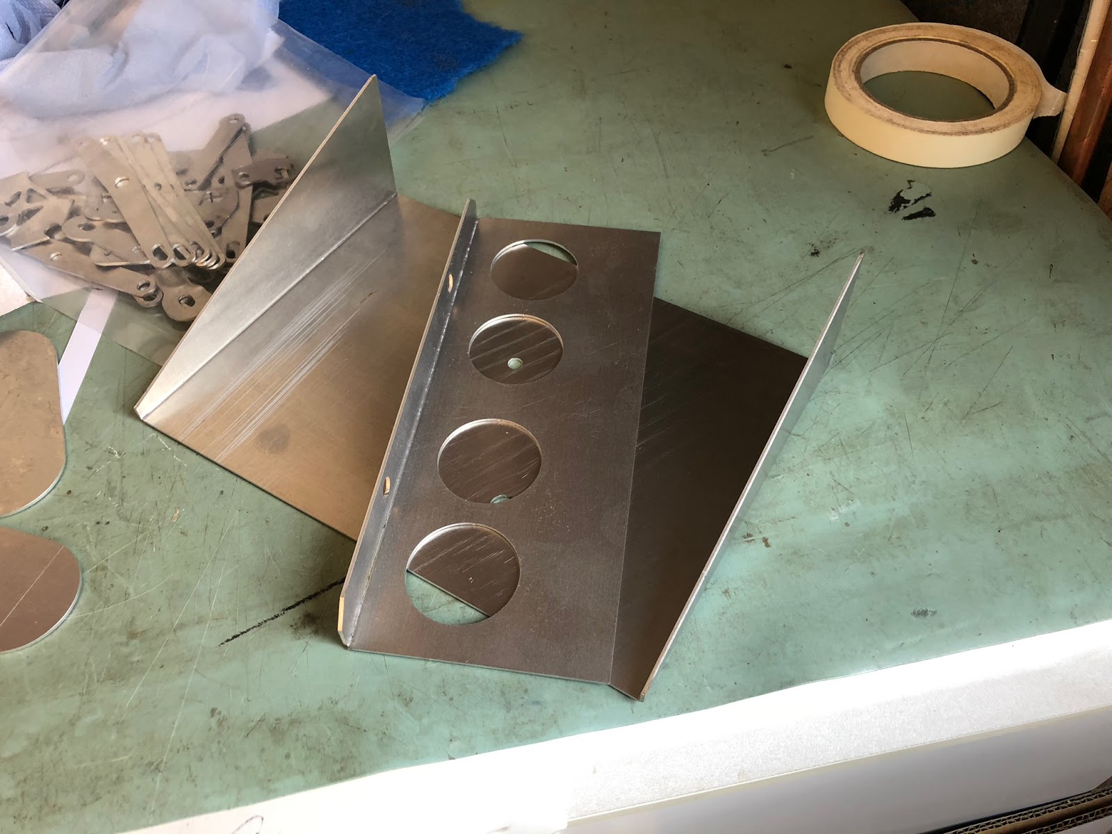
I have a small sheet metal folder/shear which has proved invaluable so images below of progress.

First parts folded. Make sure you fold them the right way else the part will be reversed!

Riveted and sealed together

Bearing bosses added for the variable baffle plates

Hose nozzles (from Screwfix)

Nozzles bonded in

The start of the internal mechanism

Bit more progress. Shame its backwards! Did I mention that you have to bend it the right way round

Parts of the deflectors

Both finally complete
I'm happy with progress and it looks to work OK too. Still got a bit to do but I'll finish that a little later.

Gearbox Mounts - Pt 1

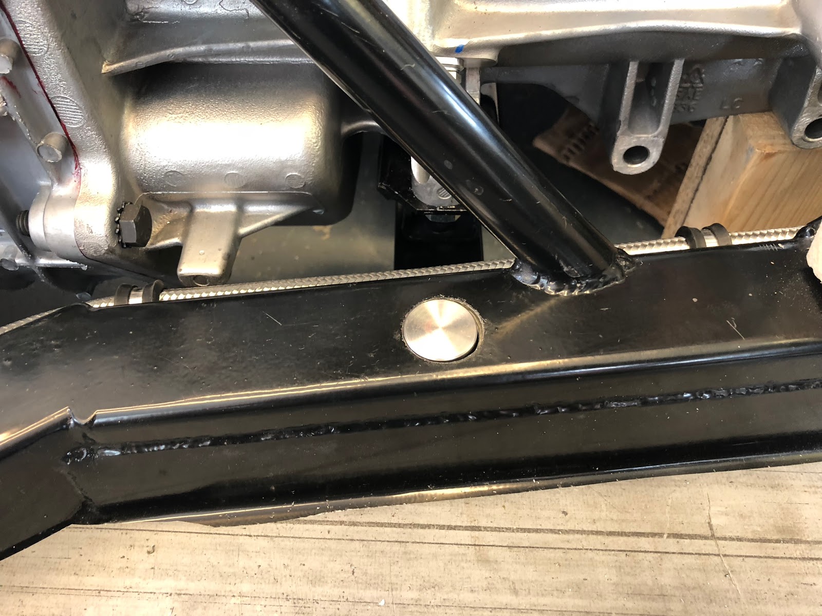
I have never been a fan of simply drilling and tapping into the chassis rails with larger screws so decided to do it a little differently. I have had a couple of bosses made that will fit in through the top wall of the chassis rail and sit on the inside of the bottom wall of the chassis rail and then be fully welded on the top surface. These pillars are 25mm diameter and have an M12 tapped hole in the bottom.

Pillars and bolts. I'll use spring washers and loctite

25mm hole in the top and 12.5 in the bottom and through the gearbox mount plate.
First one in ready for welding


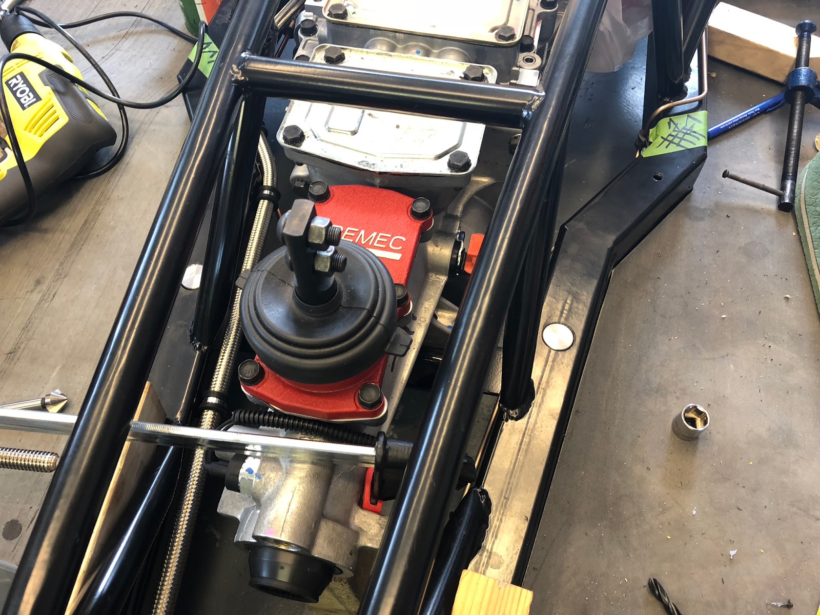
Bolted up with temporary braces removed. Just needs welding.
I'll get the welding done a little later as I want to get all necessary welding done at the same time. I will have a small boss for the handbrake cable mods, the side-pipe mount brackets and the gearbox mounts that need welding.

Engine - Pt 12

Quite a nice long update today after a bit of a lull.

Well the engine has now been run and in and setup on the dynamometer. The firing order had to be changed to 351 spec rather than 302 as I had it. The timing was set and a few setup changes on that too but the carburettor was pretty much spot on.

Peter and Knight Racing did the testing and seems happy with what I have built which is very satisfying. The results are as below.


I must say that I am really pleased with the result. More or less 450 bhp and 426 ft/lb should be adequate....

Now it needs attaching to the gearbox etc and finally fitting into the chassis.

So, onto the next task.

First thing I did was to attach the flywheel. At this point I can dial in the bell-housing to make sure the input shaft of the gearbox is less than 0.005" runout. Initially when I set it up to measure the runout it was about 0.018" out in the worse case. Now, after selection and fitting a set of offset dowels it is very much closer and fully within tolerance.

All dialled in.
0.007" offset dowels from Stateside Autos of Nuneaton.

So now I can go ahead and fit the clutch assembly not forgetting to very closely follow all assembly instructions and final torque settings. I have chosen to fit a McCloud twin plate clutch with hydraulically actuated lever arm.

Back-plate, flywheel and first part of clutch
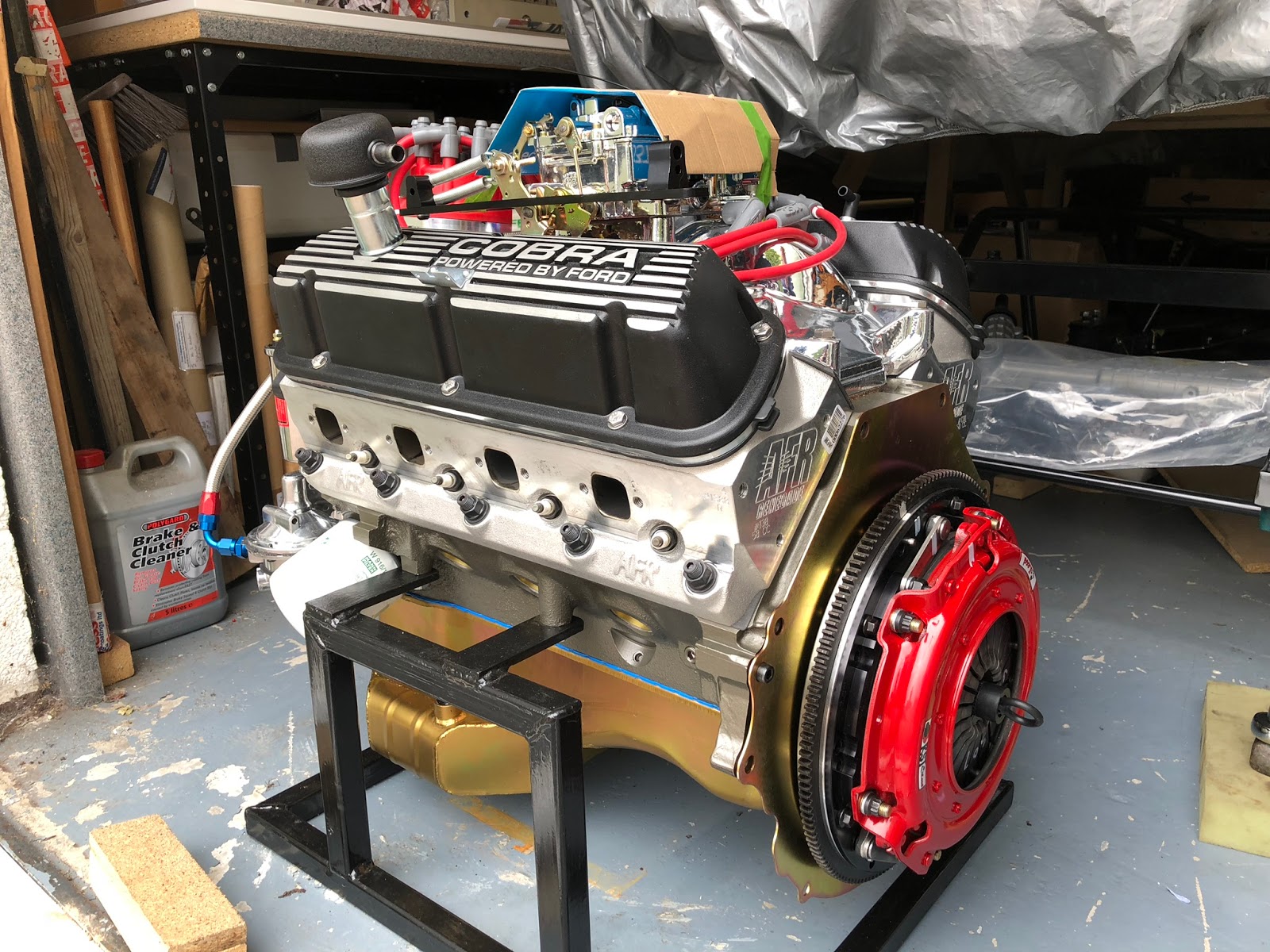
Fully fitted clutch

Pivot installed
Bell housing fitted although I have forgotten to add the actuator bracket!
Clutch release lever and bearing fitted
At this point my patience was somewhat tried. Could I get the gearbox to engage through both plates! Oh no. No chance. I had spent a lot of time making sure that all was very carefully centred and that I didn't push on the pressure plate springs when trying to fit the gearbox (which I must have done as the back plate moved.... again). In the end I gave up for the night, had a cup of coffee and relaxed only to begin battle tomorrow.

Just about to lift the and align the gearbox
Finally fitted after much effort and frustration
I ended up making some dowels out of long bolts so that I could slide the gearbox along these keeping it level and central. There were two of us doing this in the end and with Pete's help and the thought "why not depress the clutch lever, I have nothing to loose!!" it slide on so smoothly and we were able to bolt it up permanently. Boy, that was a relief to get that done. I was all ready to call it a day but Pete had come over specifically to help me get the engine/gearbox assembly into the chassis so we persevered.

In the air and removing the engine frame
Nearly in. Lots of gently manoeuvring back and forward and up and down

Nearly there although there is a clash with the fuel pump and I squashed the brake pipe. Oh well can't be helped.
Fuel pump and brake pipe issue. Needs to be sorted.

And there it is in its final position along with make shift gearbox mounts.
Finally in and fitted. Thanks Pete, couldn't have done it without you.

Monday, 23 July 2018

Front mesh - Pt 1

While I was waiting for the offset dowels to arrive following dial-in of the bell housing I thought I would have a go at the front mesh grills. Don't want the front all filled in with mesh but just the one below the rad opening and the two smaller ones either side.
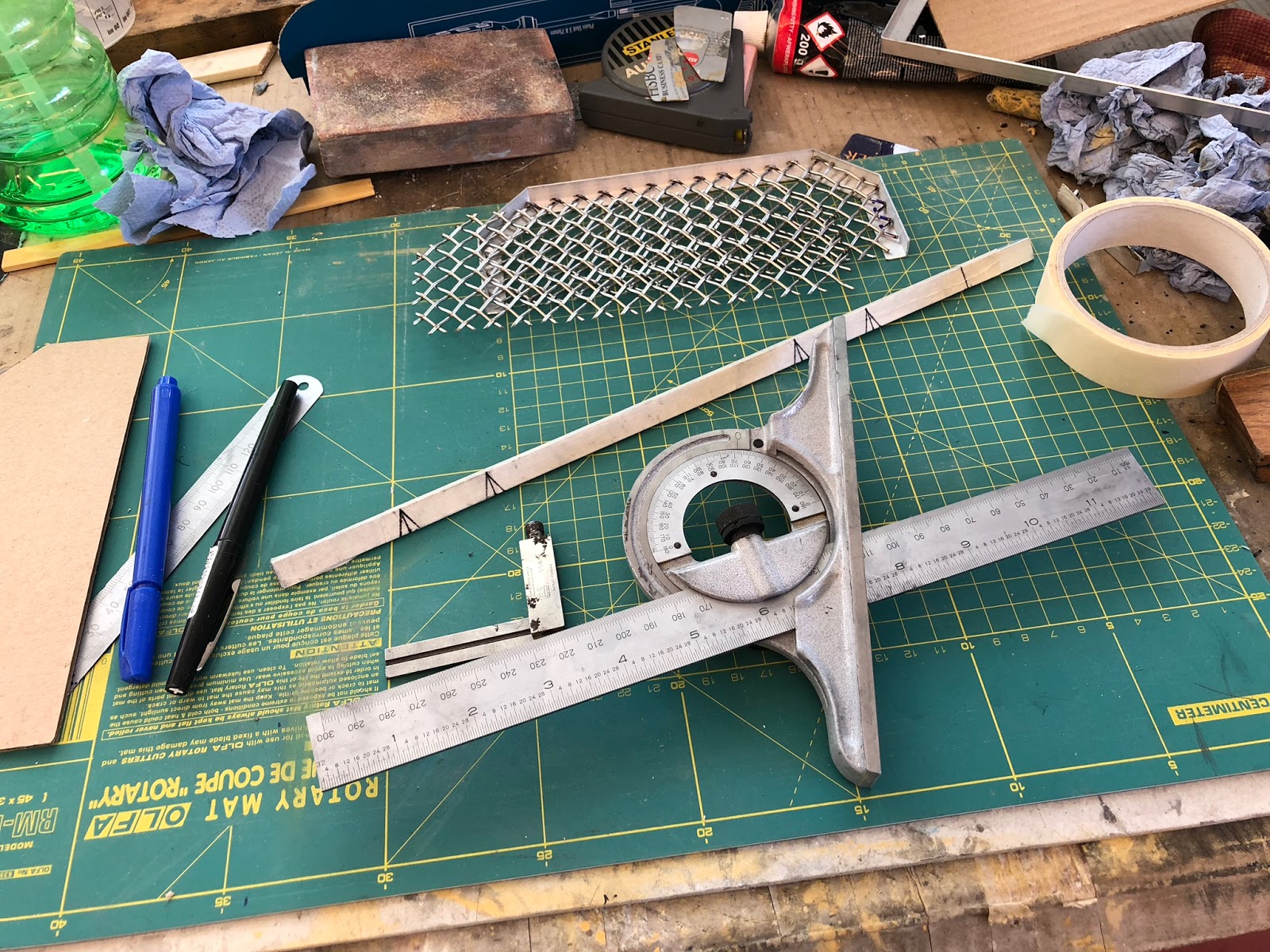
I purchases some of the Eastwood electro-polished mesh and they cut it to size for me. All I had to do was cut off the corners and make a suitable frame to carry it and fix it to the body.

I started with the one below the rad/cooler. Cut the corners off the blank that was supplied and cut and formed a small aluminium frame to carry the mesh. This could then be either bonded or bolted to the body (TBC).


I then moved onto the two side grills. These have a 3 sided frame but seem to be OK.


After the frames were completed that were all sprayed black and then the mesh was bonded to the frame using black Tiger seal.


The lower grill test fitted in its aperture. I'm really pleased with how it looks.


Monday, 18 June 2018

Lights - Pt 1

Thought I would take a break from sanding and filling of the reverse and fog light moulds. Time to look at fitting the rest of the lights front and rear so I started with the headlights. First thing to do was sort out the centre on the mount area's, sand flat and then mark out.


This proved to be relatively straight forward I'm pleased to say so I used the same process for both sides. Only really needed a little flattening over mound/split lines and the hole (already cut) needed a little bit of sanding to make round and uniform thickness.


Just had to make sure that I had the bowls up the right way. I carefully marked all the holes, piloted them and carefully drilled them with a step drill till the right size was sorted. I fastened them all with pan head cap screws, large washers and nyloc nuts. The RH photo shows the template I made for sorting the position of the indicators. I was able to cover the area on the body with masking tape and spot through the template. After this holes were cut carefully with either a stepped drill or a hole saw used with very gentle pressure.


First side light fitted. Still need to change the bulb for a mirrored style.


Front all done for now. Now onto the back.

As before I have made a template for how I want to position the lights so, after applying masking tape in the offending areas, this was careful positioned and all holes spotted through onto the tape.


There is a slight issue with the moulding on the offside as it will need a little building up for the light to fit as I want it.


So for now that's all I'm doing with the lights. Its starting to look more like a car at last.

Fog & Reverse Lights - Pt 2

Both solid plugs are ready to bond to the rear valance sections and then fill, sand, fill, sand ........ until perfect.

First one with the first coats of primer ready for final filling as I can now see the small areas that need a little work.


I'm going to fix this to a thick strong base to remove the flex from the fibre glass part. Still got a way to go but should be OK. Just got the cover to create for inside the boot but I will do that after these are fitted into the body.

Mmmm! A bit of a of warning needed here. Make sure your paints are compatible else this happen's! Lots more sanding now required. Don't make my mistake.


Oh well, practice is good. So, after much more time I am to the stage below and all is OK. Just need to fill a couple of small areas on the LH one and finish sand the other and then I will gloss and wax ready for moulding.